Breakdown Elimination
A practical guide to investigating recurring equipment failures at the component level, finding the real cause, and removing it permanently.
A breakdown that happens twice without a completed investigation is a breakdown the system has accepted.
The component fails. The technician responds. The repair is made. The line restarts. The failure is logged, if it is logged at all. And then the next call comes in. The next start-up problem. The next jam. The next breakdown. The investigation that was supposed to happen gets displaced by the work that cannot wait.
Some breakdowns are investigated. But the investigation stops at the obvious. The component failed. It was replaced. The line is running. That is enough.
It is not enough.
I worked on a line once where a shaft had broken. It took two days to get the line back up. We had a spare in stores, which was only there because the same thing had happened at least twice before. We had been lucky each time that the spare was available. We had not been curious enough to ask why we kept needing it.
This time we did a proper Breakdown Elimination investigation. We examined the failed shaft. The wear pattern was not what you would expect from a shaft that had simply reached the end of its life. The angle of the wear was wrong. We went back to the mount. It had been set incorrectly, by a small amount, a few millimetres, and that slight misalignment had been loading the shaft unevenly on every rotation, for years. The shaft was not failing because it was worn out. It was failing because it was being destroyed by a condition that nobody had looked for.
We moved the mount three millimetres. Two years later the shaft was still there, 5 years later, still there.
Without the wear analysis, we would have replaced the shaft again. We would have kept a spare in stores. We would have accepted two days of lost production every two years as the cost of running that line. The investigation would have stopped at the obvious, the shaft broke, and missed the cause entirely.
Breakdown Elimination is the discipline of not stopping at the obvious. Not just fixing what broke, but understanding why it broke, whether it has broken before, what the pattern looks like, and what needs to change so that it does not break again.
It uses the same six-stage problem solving discipline used across the system. What it adds are the tools specific to equipment failure: component-level failure classification, Mean Time Between Replacements (MTBR) charts, wear analysis, and PM Analysis. These are not replacements for structured problem solving. They are the equipment-specific layer that sits on top of it.
What Breakdown Elimination is for
Breakdown Elimination is not for every failure. It is for the failures that keep coming back.
A single, isolated breakdown on a non-critical component does not need a full investigation. A breakdown on a critical component that has failed three times in six months does. The equipment ranking tells you which components justify the depth of investigation that Breakdown Elimination requires.
The question that triggers a Breakdown Elimination investigation is simple: has this component failed before, and if so, what did the last investigation find?
If the answer is that there was no investigation, or that the investigation did not change anything, the failure is a candidate for Breakdown Elimination.
The difference between a repair and an elimination
A repair restores the component to working condition. It is necessary. It is not sufficient.
An elimination changes the system so that the component does not fail in the same way again. That might mean changing the maintenance interval. It might mean changing the component specification. It might mean changing the operating condition that was causing the failure. It might mean redesigning the access so that the lubrication point can actually be reached.
The distinction matters because repairs are visible and urgent. Eliminations are invisible and easy to defer. Every time a repair is made without an investigation, the next failure is being scheduled.
When to use it
Use Breakdown Elimination when:
- A component on ranked critical or important equipment has failed more than once in the same way
- A breakdown investigation was completed but the failure has recurred
- MTBR data shows a component is failing significantly earlier than its planned replacement interval
- A breakdown has caused a significant production loss and the cause is not immediately obvious
Do not use it for every failure. The depth of investigation that Breakdown Elimination requires is a resource. Use it where the equipment ranking and the failure history tell you it will have the most impact.
The six stages
Breakdown Elimination uses the same six-stage problem solving process used across the site. The stages are the same. The tools at each stage are specific to equipment failure.
Stage 1 — Define the failure
Before anything else, write down what actually happened.
Not what you think caused it. Not what the fix should be. The failure. The component that failed, the failure mode, the equipment it is on, the date and time, the production impact, and the failure history.
A good failure definition names the component, the failure mode — how it failed, not why — the frequency, and the production consequence. It does not name a cause. It does not propose a solution.
Use the Problem Definition guide to structure the failure statement if the problem is not yet clear. The WHO / WHAT / WHERE / WHEN / WHICH / TO WHOME / HOW and HOW MUCH framework is as useful for equipment failures as it is for any other problem. The place where the failure becomes visible is often not the place where it is happening.
Failure classification is part of this stage. Every breakdown falls into one of three categories:
- Sporadic failure: A failure that occurs once or rarely, outside the normal pattern. Investigate to confirm it is genuinely isolated before closing.
- Chronic failure: A failure that recurs at a predictable interval. The pattern is the finding. The investigation asks why the component reaches the failure point at that interval.
- Deterioration failure: A failure caused by a component that has been allowed to deteriorate past its serviceable condition. The investigation asks what maintenance standard was not in place or not being followed.
Classifying the failure before investigating it changes the investigation. A chronic failure and a deterioration failure have different causes and different countermeasures. Treating them the same produces the wrong answer.
Stage 2 — Return to Standard
Before investigating root causes, confirm whether the maintenance standard for this component exists and is being followed.
Three questions:
- Is there a maintenance standard for this component? If not, the absence of a standard may be the entire cause. Create the best-known current standard and confirm it is followed. Then check whether the failure recurs.
- Is the standard being followed? If not, find out why. Access issues, missing tools, lubrication points that cannot be reached in the time available, training gaps. Remove the barriers. Then check whether the failure recurs.
- Is the standard being followed and the failure still occurring? If yes, the standard is not sufficient. Proceed to Stage 3.
This is the most commonly skipped stage in equipment failure investigation. A component that is failing because it is not being lubricated correctly does not need a PM Analysis. It needs a lubrication standard that can actually be followed.
Stage 3 — Understand why
If the cause is not immediately obvious from Stage 2, use structured analysis to find it.
Go to where the failure happened. Look at the failed component. Look at the components around it. Look at the conditions the equipment was running in when the failure occurred. A failure investigation conducted from a desk, from memory, is not a failure investigation.
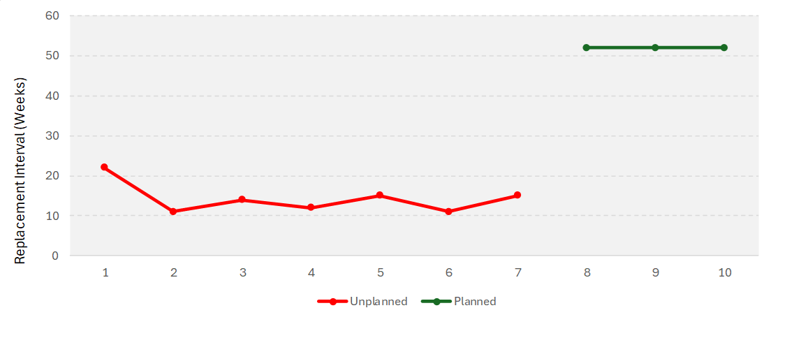
MTBR chart. Before the investigation begins, pull the failure history for this component. Plot the time between each unplanned replacement. The chart tells you two things: the average interval between failures, and the spread of that interval. A wide spread means the failure is being caused by different things at different times. A narrow spread means the failure is consistent and the mechanism is predictable. The investigation approach is different for each. A Pareto of failure modes across the history will tell you which failure type is driving the most loss, start there.
5 Whys. Ask why the component failed. Then ask why that condition existed. Keep asking until you reach a cause you can act on, a maintenance standard, a design weakness, an operating condition, or a specification that is wrong. The goal is to move from the symptom to the mechanism: the specific condition that caused the component to fail at this point in its life.
Wear analysis. For high-cost or high-consequence failures where the failure mode is not obvious from observation alone, examine the worn or failed component directly. The pattern of wear tells you how the failure happened, which points directly at why.
Five wear modes are worth knowing:
- Abrasive wear: Surface material is being removed by contact with a harder material or particle. Look for scoring, scratching, or gouging. Cause is usually contamination, incorrect material specification, or misalignment.
- Adhesive wear: Material is transferring between surfaces in contact. Look for smearing, galling, or material pickup. Cause is usually inadequate lubrication, incorrect lubricant, or excessive load.
- Fatigue wear: Cracks form and propagate under repeated cyclic loading. Look for pitting, spalling, or surface fracture. Cause is usually overload, misalignment, or a component running beyond its design life.
- Corrosive wear: Chemical attack degrades the surface. Look for discolouration, pitting, or surface roughness inconsistent with mechanical wear. Cause is usually incorrect lubricant, contamination, or environmental exposure.
- Erosive wear: Material is removed by the impact of particles or fluid. Look for smooth, rounded surface loss in the direction of flow. Cause is usually contamination in the fluid stream or incorrect material specification.
The wear mode is not the root cause. It is the mechanism. The root cause is the condition that produced that mechanism, the wrong lubricant, the misaligned shaft, the contaminated fluid. The wear pattern tells you where to look. The 5 Whys tells you why it is there.
For failures where the wear mode is still unclear after direct examination, particularly high-value components or failures with significant safety or quality consequences, metallurgical analysis by a specialist can confirm the failure mode from the material structure. This is not a routine tool. It is the right tool when the cost of getting the countermeasure wrong is high.
PM Analysis (Physical Mechanism Analysis). When the investigation has gone as far as the 5 Whys can take it and the cause is still not confirmed, go around again, but at a different level.
Rather than asking why did this happen, PM Analysis asks what physical conditions must be present for this failure mode to occur. It works backwards from the failure to the conditions that must have existed, then checks whether those conditions are actually present in the equipment. It is the same discipline as returning to Step 1 of Problem Definition with a more precise problem statement, but applied to the physics of the failure rather than the sequence of events.
Return to your failure definition from Stage 1 and sharpen it. The more precisely the failure mode is described, the more precisely the physical conditions can be identified. A vague failure description, the bearing failed, produces a vague analysis. A precise one, the inner race of the drive shaft bearing fractured under load, consistently at the drive-side face, after approximately 12 weeks of operation at full speed, gives you something to work with.
Then work through the physical conditions systematically. For each one, ask: could a condition in this category produce this specific failure mode?
- Load. Is the component carrying more load than it was designed for? Consider static load, dynamic load, shock load, and cyclic loading. Overload can come from the process itself, product weight, line speed, tension, or from the mechanical system, misalignment, imbalance, incorrect fits.
- Heat. Is the component operating outside its design temperature range? Heat accelerates wear, degrades lubricants, causes thermal expansion that changes fits and clearances, and reduces material strength.
- Pressure. For hydraulic, pneumatic, or fluid-handling components: is the operating pressure within specification? Pressure spikes, cavitation, and pressure cycling can produce failure modes that look like material fatigue or surface damage.
- Speed. Is the component running at the correct speed? Overspeed increases centrifugal forces and heat generation. Speed variation, hunting, surging, produces cyclic loading that fixed-speed analysis misses.
- Vibration. Is there vibration present that should not be there, or at a frequency that coincides with a natural frequency of the component or structure? Vibration is one of the most common hidden causes of fatigue failures and one of the easiest to miss.
- Contamination. Is the component exposed to particles, moisture, chemicals, or other contaminants? Sources include the process fluid, the environment, inadequate sealing, and maintenance activities, including the wrong lubricant introduced during a service interval.
- Lubrication. Is the correct lubricant present, at the correct quantity, reaching the correct point, at the correct interval? Check the type, quantity, delivery method, interval, and condition at the point of application.
- Fit and alignment. Is the component correctly fitted and aligned? Misalignment introduces loads the component was not designed to carry. Incorrect fits change the stress distribution and can cause fretting, fatigue, or seizure.
- Material and specification. Is the component the correct specification for this application? A substituted grade, supplier, or surface treatment may behave differently under the same conditions.
List every condition that could plausibly produce the failure mode. Do not filter yet.
Then go to the machine and check each one. Measure. Do not assume. For each condition, determine whether it is present, absent, or unknown. Unknown means it has not been measured, not that it is not there.
The conditions that are both physically capable of producing the failure mode and actually present in the equipment are the candidates for root cause. The 5 Whys then takes over from there, why is that condition present, and what needs to change to remove it, feeding back into Stages 4 and 5 of the main process.
PM Analysis is not a quick tool. It is the right tool when the failure is genuinely difficult to explain and the cost of getting the solution wrong is high enough to justify the depth of investigation it requires.
Stage 4 — Select the solution
Once the cause is confirmed, identify the possible solutions and choose the right one.
The solution must address the confirmed cause, not the symptom. A countermeasure that reduces the visible impact of the failure without changing the mechanism is a workaround. It will need to be applied again.
Use an impact vs. effort assessment to evaluate options before committing. The solution that addresses the mechanism with the least disruption is the starting point. A design change may be the most permanent solution but the most resource-intensive. A maintenance interval change may be achievable immediately. Both may be right, in sequence.
Types of solution for equipment failures:
- Maintenance standard change: The interval, the method, the lubricant, the specification. The most common solution for deterioration failures.
- Component specification change: A different material, a higher-grade component, a design modification. The most common solution for chronic failures where the component is reaching the end of its life too quickly.
- Operating condition change: A speed, a temperature, a pressure, a load. Where the failure is caused by the equipment being run outside its designed operating range.
- Access improvement: Where the maintenance standard cannot be followed because the component cannot be reached. The solution is not to accept the inaccessibility. It is to remove it.
- Design change: Where the component or the system has a fundamental weakness that cannot be addressed by any of the above. The most resource-intensive solution, and the most permanent.
Do not select the first solution that comes to mind. Generate options. Evaluate them against the confirmed cause. The solution that addresses the mechanism is the right one, regardless of how obvious a different option might seem.
Stage 5 — Validate the fix
Before declaring the failure eliminated, confirm that the solution is what produced the improvement.
For equipment failures, the primary validation method is MTBR tracking. After the solution is implemented, track the time to the next replacement for this component. Compare it to the pre-countermeasure average. If the interval is extending, the solution is likely working. If the component fails at the same interval, the solution has not addressed the mechanism.
This takes time. A component that was failing every six weeks will not confirm the solution in a week. Plan the validation period before the solution is implemented, and track it deliberately.
Where the solution can be tested more quickly, a lubrication standard change, an access improvement, a specification change, use on/off testing where it is safe to do so, or a before-and-after comparison with enough data to distinguish the solution's effect from normal variation.
Do not declare a failure eliminated because the component has not failed since the solution was implemented. That is not validation. That is waiting. Validation is a deliberate comparison of pre- and post-solution MTBR data.
Stage 6 — Make it stick
A solution that is not built into the system will not hold.
To ensure the solution will stick, three things must be in place. Remove any one of them and the failure will return.
Updated planned maintenance schedule. If the maintenance interval changed, the planned maintenance schedule must reflect it. A standard that says one interval and a schedule that runs a different one will produce the failure again. Both must be updated together.
Reapplication check. Ask whether the same failure mode exists on similar equipment elsewhere on the site. If the same component is used on multiple lines and the failure mechanism is a design weakness or a specification issue, the solution applies to all of them. Do not wait for the failure to recur on the next line before applying what was learned here.
The finding and the solution are documented and shared. Not in a folder. In the maintenance standard, the planned maintenance schedule, and the equipment history in the maintenance management system. The next technician who works on this component should be able to see what failed, what was found, and what was changed.
MTBR charts — how to use them
The MTBR chart is the primary analytical tool in Breakdown Elimination. It is simple. It is powerful. It is almost never used.
Plot the time between each unplanned replacement for a specific component on a specific piece of equipment. Each data point is the number of days or weeks between one replacement and the next. Plot them in sequence.
What the chart tells you:
- The average interval. This is your baseline. It tells you how long the component is currently lasting. Compare it to the planned replacement interval. If the component is failing significantly earlier than planned, the planned interval is wrong, the maintenance standard is not being followed, or the operating conditions are causing premature failure.
- The spread. A wide spread means the failure is being caused by different things at different times. A narrow spread means the failure is consistent and predictable. Narrow-spread failures are easier to investigate and easier to eliminate.
- The trend. Is the interval getting longer or shorter over time? A shortening interval means the equipment condition is deteriorating. A lengthening interval means the solutions are working.
The chart is also the validation tool. After a solution is implemented, the next data points should show a longer interval. If they do not, the solution has not addressed the mechanism.
A Pareto of failure modes alongside the MTBR chart adds a second dimension: not just how often the component is failing, but which failure mode is driving the most replacements. If three different failure modes are appearing across the history, the investigation needs to address each one separately. Treating them as one problem produces a solution that addresses one cause and leaves the others untouched.
What this gives you
Common pitfalls
Key Links
Breakdown Elimination is built on the Problem Solving discipline used across the site. The six stages are the same. The tools at each stage are specific to equipment failure.
The Problem Definition guide covers how to write a specific, measurable failure statement before the investigation begins.
Equipment ranking determines which components justify the depth of investigation that Breakdown Elimination requires.
MTBR is the primary output measure of Breakdown Elimination's effectiveness. It is reviewed at the Tiered Accountability Meeting as a Hypercare process on critical equipment.
Process Confirmation is how the updated maintenance standard is confirmed to be in place and being followed after the solution is implemented.